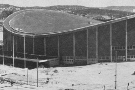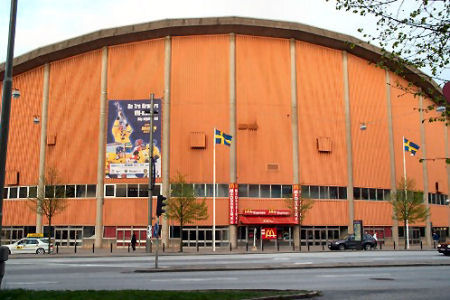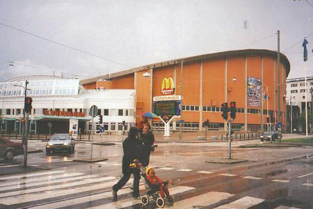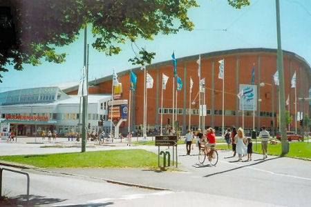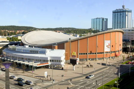
Scandinavium Arena, Gothenburg, Sweden, 1971
Architect: Poul Hultberg
Engineer:
Credits:
Gunnar Tibert
In 1948 an architect competition concerning an indoor sports building in central Gothenburg was announced. It was won by a working group led by the architect Poul Hultberg. In 1962 the preliminary design works started and a final decision concerning the realization of the structure was taken in June 1969. In May 1971 the Scandinavium Arena was completed. With space for 14000 spectators it was at the time the largest covered arena in northern Europe.
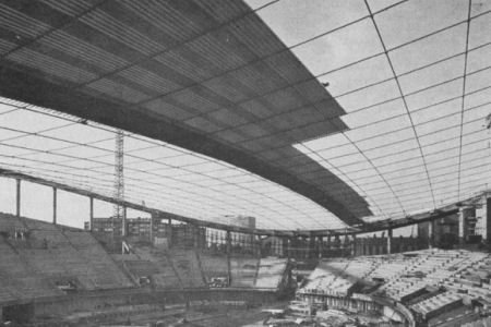
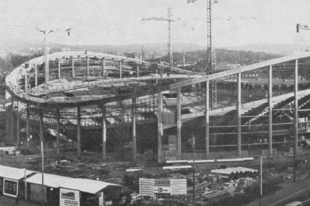
Roof structure: The roof consists of a prestressed cable net cladded with thermal and water insulated corrugated steel plates. All cables are anchored in a reinforced concrete ring. The concrete ring is supported by four stiff pylons and 40 circular columns. The surface of the roof conforms nearly to a hyperbolic paraboloid. From the centre point of the roof the hanging cables rise 10 m to the top and the bracing cables fall 4 m to the valley of the ring. The cable spacing is nearly constant and equals to 4 m in both directions.
Foundation: The building is supported partly by rock and partly by concrete piles. Two of the pylons are supported by concrete foundations that rest on 115 piles. The large number of piles needed is due to the horizontal forces that occur at the connections between the ring beam and the pylons.
Ring beam: The ring beam has a rectangular cross-section with a width of 3.5 m and a height of 1.2 m. An alternative solution with a ring beam made as a hollow steel box was investigated during the design work, but it was found to be too expensive.
Columns and pylons: The circular columns are cast in place and designed to carry mainly axial forces. The pylons consist of radially oriented concrete walls, with a side length of 3.5 m connected by beams, Figure 5.2. The space between the walls is approximately 3.5 m wide and filled with ventilation equipment. The pylons are relatively stiff and can take large horizontal forces. Therefore, the ring beam is discontinuous at the top of the pylons which affects the prestressing forces in the cable in the areas between the pylons and the top of the ring beam. The forces in the bracing cables are there significantly smaller than in other parts of the roof.
Tension rods: The light and sound systems are suspended in a cable system supported by the pylons. This radially oriented cable system also serves as tension rods for the ring beam, which is discontinuous at the pylons.